Electrical Basics

One of my hobbies is electrical/electronics. I’ve been looking at getting an apprenticeship for the electric trade here in Australia (with very little luck) and have spent a bit of time relearning much of what I had forgotten due to other commitments (study, sporting, work, etc.).

I have decided to make a post here for anyone who would like to share resources or to ask questions, and I’ll try to help as best I can (bearing in mind that I am also barely out of beginner level (having regressed after not practising a great deal).

Basically this topic will consist of Resources, Suppliers, Tutorials, Explanations, Projects (actual or conceptual), and help/materials (offered or wanted/WTS or WTB). Feel free to link to any relevant blogs or websites that might help.

For some basic tutorials, I recommend going through SparkFun’s tutorials and searching the topic you want to learn. You can also look at the SparkFun Blog for some inspiration and information on new SparkFun products. I also recommend SparkFun’s YouTube channel, although most of their stuff is geared towards the use of micro-controllers.

Magazines I find helpful:
Silicon Chip
Diyode Magazine
Nuts and Volts
Servo Magazine

All of these websites have some project ideas, tutorials, and inspirations for you to look at.

Suppliers:
Jaycar - as with a couple of others, it is partnered with Arduino and RaspberryPi, so their workshop gives you some project ideas to get you started (they only started it recently)
SparkFun
Jameco
Digikey - also has some helpful resources and online tools (especially calculators for the various formulae)
Pololu
Tronixlabs - eBay store-front

To start, I recommend reading some of SparkFun’s tutorials on the basics and avoid using micro-controllers (micro:bit, Arduino, and RaspberryPi) until you need them. You can also look up most of this stuff in a general search on Google (and Wikipedia), but SparkFun is probably the most helpful starting point.

To get started, we need to clarify some terms: what are electricity, voltage, power, current, and resistance and how do we measure and calculate them?

Electricity:

Electricity is a natural phenomenon that occurs throughout nature and takes many different forms. In this tutorial we’ll focus on current electricity: the stuff that powers our electronic gadgets. Our goal is to understand how electricity flows from a power source through wires, lighting up LEDs, spinning motors, and powering our communication devices.

Electricity is briefly defined as the flow of electric charge, but there’s so much behind that simple statement. Where do the charges come from? How do we move them? Where do they move to? How does an electric charge cause mechanical motion or make things light up? So many questions! To begin to explain what electricity is we need to zoom way in, beyond the matter and molecules, to the atoms that make up everything we interact with in life.

This tutorial builds on some basic understanding of physics, force, energy, atoms, and fields in particular. We’ll gloss over the basics of each of those physics concepts, but it may help to consult other sources as well.

Voltage, Current, and Resistance:

Electricity is the movement of electrons. Electrons create charge, which we can harness to do work. Your lightbulb, your stereo, your phone, etc., are all harnessing the movement of the electrons in order to do work. They all operate using the same basic power source: the movement of electrons.

The three basic principles for this tutorial can be explained using electrons, or more specifically, the charge they create:

  • Voltage is the difference in charge between two points.
  • Current is the rate at which charge is flowing.
  • Resistance is a material’s tendency to resist the flow of charge (current).

So, when we talk about these values, we’re really describing the movement of charge, and thus, the behavior of electrons. A circuit is a closed loop that allows charge to move from one place to another. Components in the circuit allow us to control this charge and use it to do work.

Georg Ohm was a Bavarian scientist who studied electricity. Ohm starts by describing a unit of resistance that is defined by current and voltage.

Power:

In general physics terms, power is defined as the rate at which energy is transferred (or transformed).

So, first, what is energy and how is it transferred? It’s hard to state simply, but energy is basically the ability of something to move something else. There are many forms of energy: mechanical, electrical, chemical, electromagnetic, thermal, and many others.

Energy can never be created or destroyed, only transferred to another form. A lot of what we’re doing in electronics is converting different forms of energy to and from electric energy . Lighting LEDs turns electric energy into electromagnetic energy. Spinning motors turns electric energy into mechanical energy. Buzzing buzzers makes sound energy. Powering a circuit off a 9V alkaline battery turn chemical energy into electrical energy.

You will also need to be able to Read a Multimeter and Interpret Schematics.

The final part to this post is two-fold:
First, the two types of Current;
Second, the basic components: Switches, Resistors, Transistors, Capacitors, LEDs, Diodes, and Integrated Circuits.

You will also need to get your hands on a Breadboard, Wires, and a Power Supply of some description (Batteries can work pretty well, but I recommend a good, cheap Breadboard Supply that works well to get started.)

1 Like

Great post. Electronics has always been one of the things that surpasses me, and anything with connectors n’ grounds n’ voltages n’ stuff surpasses me.

I will let you know if I ever have some problem with any electricity-related project

2 Likes
Apologies for the delay, I have been revising and relearning much of this in preparation for writing some longer explanations/tutorials of my own. I also plan on writing up some basic projects which you can use for practice. They'll just be very basic stuff to start off with, but I hope to move on to using integrated circuits and micro-controllers fairly quickly (as mentioned in the first post, however, it is better to avoid using the micro-controller until you need it, since much of what I want to focus on right now can be accomplished with more basic components.) If anyone either knows more than I or is unclear on something I have written, I encourage you to let me know and feel free to add your own content et al.

For today, I’m going to focus on the 4 main terms to understand before working on anything else, Voltage, Current, Resistance, and Power.

Voltage ( V ): Voltage is the electrical pressure used to supply power throughout a circuit. For mathematical work, Voltage is measured in Volts and signed by the pronumeral V.

Current ( I ): Is the movement of electrons through a conductor. For mathematical work, current is measured in Amperes (abbrev. Amp) and is signed by the pronumeral I. There are two types of current, Alternating Current (AC) and Direct Current (DC).

Resistance ( R ): Is the reduction of voltage and current in a circuit. For mathematical work, resistance is measured in Ohms and signed by the pronumeral Ω.

Power ( P ): is the output of a circuit. For mathematical work, power is measured in Watts and signed by the pronumeral W.

To explain this by way of example I will use the basic lighting circuit in a house.

Cables run from the mains electricity box (usually located outside the house), through the roof-space and/or walls to a switch, and each switch connects to a light-socket. The switch provides an insulated control for the user so that there is, in theory, no risk to the user when they are switching a light on or off. When in the “Off” position, the circuit is open, so whilst there is voltage applied along the cables to the switch, there is no connection between the active and neutral wires, therefore, there is no current. When the switch is moved to the “On” position, the circuit closes and the voltage from the mains input can push the current along the active and neutral wires up through the light-bulb. A light-bulb filament provides a certain amount of resistance so that when the current and voltage cross it, it outputs power as heat and light.

An analogy of sorts can be drawn from the working of electricity to the common garden hose. When the tap/faucet is closed, the water cannot flow through the hose. When the tap/faucet opens, the pressure (voltage) is able to push the water through the hose and out the end (current). If you were to place a thumb over the end or crimp the hose somewhere (resistance), the pressure inside would increase (Bernoulli’s Theorem stating that a high pressure equates to a low speed and a low pressure to a high speed) which would decrease the rate at which the water flowed. You would also notice an increase in tension on the hose or a pushing against your thumb, this is similar to the power output of a circuit. Whilst there are differences between water and electricity, thinking of things as working in this way is helpful when making distinctions or trying to understand what is happening.

To explain the maths behind these four terms, it helps to have on hand an aid such as this:

Power_And_Ohms_Law

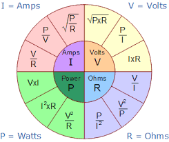
In the primary example, you can work out the power output of the light-bulb by substituting P = V * I for whatever voltage and current values are used in your country (for me, 240V * 10A = 2400W (which can be shortened to 2.4kW*)). The value you get here may seem quite high, but this example assumes that there is no circuit resistance. If you want a more accurate reflection of reality, transpose the problem by finding the power dissipation on the light-bulb (it should be written on the component, if not, you can use a multimeter to read the resistance of it) and working backwards: I = P / V. Taking the example of a 60W bulb, I would work it out thus: P / V = I (since I now know my power to be 60W and my voltage to be 240V), 60W / 240V = 0.25A or 25mA.


*A note on the International System of Units (SI) and Scientific Notation: When working with electricity, numbers can get quite large or incredibly small. To make things easier, we express things using the International System of Units (or SI). The standard abbreviations you may see are GV, MV, kV, V, mV, µV, nV, or pV (using Volts (V) as an example). These stand for Gigavolts (1 * 10^9), Megavolts (1 * 10^6), kilovolts (1 * 10^3), volts (1 * 10^0), millivolts (1 * 10^-3), microvolts (1 * 10^-6), nanovolts (1 * 10^-9), and picovolts (1 * 10^-12). More information can easily be procured by searching for any of these terms on Wikipedia.

Sorry for the delay here, I’ve been busy working on a home reno and don’t have access to my workbench right now, so I’ve fallen behind on what I wanted to work on. I’m hoping that I’ll be able to start again next week.

In the meantime, a brief outline of what I hope to do over the next few posts: I plan to put together a few basic projects, if I can think of a good format, I might do them as videos, posted to YouTube and then shared here, but more than likely, I’ll start of by taking photos and describing what is to happen in each step. The projects will start of simply with safely connecting a basic LED circuit, making an LED blink, and then going into more detail on how these circuits work.

The first circuit will be the most basic, in terms of what’s used and what happens: It’ll be a battery, a resistor, the LED, a switch or button, and the relevant number of wires to complete the circuit.
The second will try to better explain what effect the resistor has throughout the circuit and how we can use these better in circuits.
The third will introduce transistors and capacitors, demonstrating how they can work in a circuit.

After this, I plan to go into things like transistor-transistor logic (TTL) and resistor-transistor logic (RTL), which can be used to make basic logic gates (such as AND, OR, etc.). As needed, I’ll move into using CMOS logic (currently I only use 4000 series logic, but I plan to move into using 74 series logic soon), which will add new forms of logic to our circuits, on top of the TTL and RTL already being used.


I have, recently, acquired some small modules such as a DC-DC boost-converter, a 20W power converter, and an adjustable switching power supply, so with any luck, I’ll be able to show you how to use these and then some higher voltage projects.


At the end of this series of posts, I’m hoping that you who have an interest in electronics feel comfortable sharing your own projects and knowledge in an effort to teach more people in this community how to move further away from government and big corp/tech involvement. It is also my opinion that men need to have hobbies but that the modern world, with its strong push against independence in thought and deed, has lessened men’s access to the resources he needs to get started.

There are a lot of websites out there where more qualified and practised people can provide answers, such as the Electrical Engineering Stack Exchange forum, but I hope that you’ll share your questions and knowledge here too so that others can learn.

1 Like